Azimuth movement
It consists of determining the desired direction on the ground at a given azimuth and maintaining this direction along the way until reaching the intended point. During a hike, movement in azimuth is usually resorted to in closed areas or off-road, for which magnetic azimuths and distances to landmarks are determined in advance using a map.
Movement using intermediate landmarks
When moving in azimuth, the practical accuracy of reaching a landmark is usually up to one tenth of the route traveled. Therefore, it is always advisable to mark intermediate landmarks along the route. To do this, before moving, set the compass sighting device to the desired direction and orient the compass . Then they sight in the desired direction (or near it) some clearly defined and not very distant landmark, towards which they move. Having reached the landmark , the operation is repeated again. When determining the direction, you must ensure that the northern end of the compass needle coincides with the north mark on its dial.
This is interesting: How to determine the numerical scale of a map
When moving in azimuth, tourists may encounter significant obstacles along their path, such as a lake or a rocky area. To strictly maintain the general direction, it is advisable to go around them along a broken straight line with the least number of “elbows”. When walking around, you should clearly record the values of intermediate azimuths and the distances traveled along them.
In order not to stray from the right direction, it is useful to draw on a piece of notebook paper (on a tablet) while moving, a detour path with angles and lengths of “knees”.
Movement without clear guidelines
In the absence of landmarks
In the field, tundra, steppe, where there are no landmarks , or in poor visibility, you can move using the alignment method . The tourist leading the movement controls the direction, being at the end of the group: he sees the entire chain of tourists, can compare its direction with a given azimuth and promptly warn about deviations.
If there is a sun (moon, stars), you can move in azimuth by measuring the angle of direction relative to these celestial bodies. Every half hour their position in the sky must be clarified using a compass. Of the techniques for such orientation, the most common is orientation by one's shadow.
In windy weather, it is useful to remember the direction of the wind or the movement of clouds relative to the sides of the horizon.
In wide open spaces in winter, snow sastrugi can be used to guide movement. In a densely forested area, in order to maintain direction, it is recommended to alternately bypass the encountered obstacles - trees, bushes, rubble - either from the left or from the right.
Sometimes, in the absence of intermediate landmarks, it is useful to make a deliberate deviation in a certain direction from a given azimuth. Having covered the distance calculated in steps or according to the time of movement to the final landmark, tourists turn sharply to the side and look in a new direction (one, and not in two opposite ones, as would be the case if they were moving straight along a given azimuth) for the desired point on the ground.
For large distances, it is necessary to mark out limiting (lateral) landmarks, and choose the final landmark as linear as possible and such that it is deployed with a wide front towards the direction of movement of tourists.
Preparation using a data card for movement in azimuths
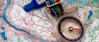
Preparing data for movement along azimuths is carried out using a large-scale map and includes studying the area, selecting a route and landmarks along its sections, determining magnetic azimuths (directional angles) of directions and distances between selected landmarks, recording data on a map or drawing up a movement diagram (table).
When studying the terrain in the direction of movement, they mainly evaluate its permeability, camouflage and protective properties, determine difficult and impassable obstacles and ways to bypass them.
Choosing a route and landmarks. The outline of the route depends on the nature of the terrain, the presence of landmarks on it and the conditions of the upcoming movement. The main requirement for the route is that it provide quick and, in a combat situation, covert access to the specified point.
The route is chosen in such a way that it has a minimum number of turns. The route includes roads, clearings and other linear landmarks, the direction of which coincides with the direction of movement. This will make it easier to maintain the directions of movement. Route turning points are marked at landmarks that can be easily identified on the ground (for example, tower-type buildings, road intersections, bridges, overpasses, geodetic signs).
When choosing landmarks on sections of the route, it is necessary to take into account the method of maintaining the direction of movement and the accuracy that it provides. For example, the accuracy of maintaining the direction of movement using a compass is 0.1 of the distance traveled. If the distance between landmarks on a section of the route is 6 km, then when reaching the next landmark the deviation may be 600 m. Finding a landmark on the ground in this case will take a lot of time.
It has been experimentally established that the distances between k landmarks along the route should not exceed 1-2 km when traveling on foot during the day. For driving at night, landmarks are marked along the route more often. To ensure a secret exit to a specified point, the route is marked along hollows, tracts of vegetation and other objects that provide camouflage of movement. Avoid traveling on high ridges and open areas. An approximate route selection option is shown in Fig. 3.6.
Determination of magnetic azimuths. The magnetic azimuth of the direction to a local object can be determined from the directional angle measured on the map or the true azimuth of this direction.
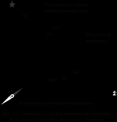
When converting the directional angle (true azimuth) into magnetic azimuth, the direction correction (magnetic declination) for a given map sheet is taken into account. The relationship between magnetic azimuth, directional angle and true azimuth is shown in Fig. 3.7. Directional angle () – the angle between the north direction of the vertical grid line on the map and the direction to the object (landmark), measured clockwise. It can have a value from 0 to 360°.
True azimuth (A) is the angle between the north direction of the true meridian (the side of the map frame) and the direction to the object, measured clockwise. True azimuth, like the directional angle, can have values from 0 to 3600.
Meridian convergence (Sb) is the angle between the north direction of the true meridian and the vertical grid line. On topographic maps of the USSR, the convergence of the meridians does not exceed ±3°.
Magnetic declination (Sk) is the angle between the northern direction of the true meridian and the direction of the magnetic meridian (magnetic needle). If the northern end of the magnetic needle deviates from the true meridian to the east, the magnetic declination is considered positive, and to the west - negative.
Direction correction (DC) is the angle between the direction of the vertical grid line and the magnetic meridian. It is equal to the algebraic difference between the magnetic declination and the convergence of the meridians:
Mon = (± Sk) - (± Sat).
Data on magnetic declination, meridian convergence, and direction correction are placed under the south side of the frame of each sheet of a large-scale topographic map. The transition from directional angles (true azimuths) measured on the map to magnetic azimuths is carried out according to the formulas:
Am = – (±PN);
Am = A – (±Sk).
Measurement using a map of directional angles. Directional angles of directions to local objects (landmarks) are measured on the map with a protractor or an artillery circle. They provide angle measurement accuracy with an error of ±1-2°.
Using a protractor, the directional angle on the map is measured in the following sequence:
· the landmark at which the directional angle is measured is connected by a straight line to the standing point so that the straight line intersects at least one vertical line of the coordinate grid. If the landmark and the standing point are located in the same grid square, then this line is continued until it intersects with the vertical grid lines of other squares;
· apply the protractor to the grid line, as shown in Fig. 3.8, and count the directional angle using the protractor.
In our example, the directional angle from point A
(individual stone) to point
B
(individual tree) is 60°, and the directional angle from point
A
to point C (geodesic point) is 302°.
The artillery circle is a celluloid plate, on the outer cut of which there is a scale in protractor divisions. The price of one division is 0-10. Large divisions corresponding to 1-00 are numbered from 0 to 60; in this case, a row of red numbers is printed in ascending order clockwise, and a row of black numbers is printed counterclockwise.
When measuring the directional angle, the artillery circle is installed on the map so that its center coincides with the intersection point of the line of the determined direction and the vertical line of the coordinate grid, and the zero line coincides with the northern direction of this line. Then a reading is taken on the red scale of the circle against the line of the determined direction.
Measurement of true azimuths on a map is carried out with a protractor or artillery circle in the same way as measurement of directional angles. In this case, the angle is measured at the point of intersection of the true meridian with the direction to the object. The line of the true meridian in this case can be either one of the sides of the map frame - western or eastern, or a line drawn parallel to it.
When converting true azimuth to magnetic, add the value of the magnetic declination to the measured angle if it is western, or subtract this value if the declination is eastern. The resulting magnetic direction azimuths are written on a map (see Fig. 3.6), in a table or on a route diagram.
Measuring distances. Distances between landmarks selected along the route are measured along straight lines using a measuring compass and a linear scale or a ruler with millimeter divisions.
Drawing up a diagram and table of movement by azimuths. The diagram is drawn up in the following sequence:
· transfer the starting point, landmarks at the turning points and the end point of the route from the map onto a blank sheet of paper. The location of landmarks on the diagram should be similar to their position on the map. All landmarks are depicted on the diagram with the same symbols as on the map;
· landmarks transferred from the map to the diagram are numbered and connected by straight lines;
· opposite each line, write down the initial data for the movement in the form of a fraction: in the numerator - magnetic azimuths, in the denominator - distances in meters. If movement along azimuths will be made on foot, and the leader’s step size is known, then the distances in meters are converted into pairs of steps and written out on the diagram in parentheses;
· put a north-south arrow on the diagram and additionally show landmarks to the side of the route, as well as in the direction of the route, which can be used during movement as intermediate or auxiliary landmarks.
In relation to Fig. 3.6 the table will have the following content (Table 3.1).
Table 3.1
| Point number | Track section | Magnetic azimuth (Am), deg | Distance, m | Distance, a couple of steps |
| Northern outskirts of Nikitskoye - ford | ||||
| Ford – intersection of a clearing with a forest road | ||||
| The intersection of a clearing with a forest road - a separate stone | ||||
| Separately lying stone - bridge |
In cases where it is necessary to maintain only the general direction of movement, for example, the direction of advance, a movement diagram (table) is not drawn up. The azimuth of the direction of movement is determined directly on the ground using a compass and is announced orally.
Night navigation: moving in azimuth in the dark
Before starting to move, the intended route should be carefully studied and, if possible, remembered so that there are as few calls to the map as possible. When operating on a route at night, the car driver is warned in advance about upcoming landmarks; to illuminate the map along the way, you will need a reliable pocket flashlight equipped with a blue filter. This light does not blind your eyes and allows you to simultaneously observe your surroundings.
Off the road, movement in azimuth is carried out using a compass (as regards direction), while the length of the distances traveled can be determined by the car's speedometer. Difficulties lie in the need to strain your eyesight and problems with recognizing local objects. Often at night you have to navigate by celestial bodies - the stars or the moon. A mandatory allowance must be made for the fact that all of them, not counting the North Star, tend to move across the sky.
Terrain orientation by azimuths. Magnetic azimuth. Determination of azimuths to local objects
Terrain orientation by azimuths
The direction azimuth from the standing point to a local object is called direct magnetic azimuth . In some cases, for example, to find the return path, a reverse magnetic azimuth is used, which differs from the direct one by 180°. To determine the reverse azimuth, you need to add 180° to the forward azimuth if it is less than 180°, or subtract 180° if it is greater than 180°. In Fig. the return azimuth is 150°.
To determine the direction on the ground based on a given magnetic azimuth, it is necessary to set a reading on the compass scale opposite the front sight that is different to the value of the given magnetic azimuth. Then, releasing the brake of the magnetic needle, turn the compass in a horizontal plane so that the northern end of the needle is positioned opposite the zero division of the scale.
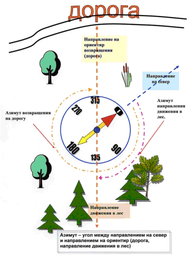
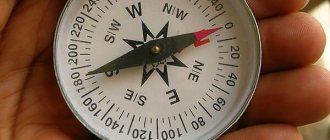
Determination of magnetic azimuth by compass
After this, without changing the position of the compass, notice some distant landmark on the ground along the line of sight through the rear sight and front sight. The direction to the landmark will be the determined direction corresponding to the given azimuth.
The alignment of the sighting line with the direction towards the object (target) is achieved by repeatedly moving the gaze from the sighting line to the target and back. It is not recommended to raise the compass to eye level, as this reduces the accuracy of the measurement. The accuracy of measuring azimuths using Andrianov's compass is plus or minus 2-3°.
Magnetic azimuth. Determination of azimuths to local objects
The direction to the object (target) is determined and indicated by the magnitude of the horizontal angle between the initial direction and the direction to the object (target) or magnetic azimuth. In this case, the direction to one of the sides of the horizon or to a clearly visible distant local object (landmark) can be taken as the initial direction.
Magnetic azimuth is the angle from the north direction of the magnetic compass needle to the direction to the object (subject). Counted strictly clockwise.
Its values can be from 0° to 360°.
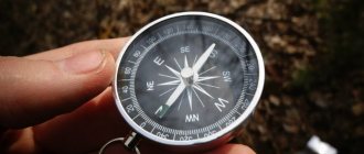
Magnetic direction azimuth is determined using a compass.
At the same time, the brake of the magnetic needle is released and the compass is turned in a horizontal plane until the northern end of the needle is positioned against the zero division of the scale.
Then, without changing the position of the compass, install the sighting device so that the line of sight through the rear sight and front sight coincides with the direction of the object. The scale reading against the front sight corresponds to the value of the determined magnetic azimuth of the direction to the local object. Tags: military topography
Features of movement along azimuths by car.
The direction of movement, given by the magnetic azimuth, is determined using a compass, located no closer than 10 meters from the car and 30-40 meters from the tank. Having noticed a distant (auxiliary) landmark in a given direction, they drive the car towards it and count the distance to the turning landmark using the speedometer. Here the car is stopped and these actions are repeated again.
When driving along azimuths by car, when there are no landmarks or they are not visible, you can use a compass. The use of a magnetic compass directly in a car is very limited. The magnetic needle, under the influence of the magnetic field of the machine, deviates from the direction of the magnetic meridian. The magnitude of this deviation (compass deviation) is not constant and depends on the metal mass of the machine, its electromagnetic field, direction of movement and engine speed. Therefore, you can use a compass in a car only after first determining its correction for a given direction of movement.
In practice, it is not the correction that is determined, but the azimuth reading along the compass, taking into account the correction. To do this, set the machine in a given direction, take a place in it as far as possible from the battery, and use a compass to measure the magnetic azimuth of the longitudinal axis of the machine. That is, the azimuth of the direction of movement.
Having started moving along azimuths, you need to make sure that the magnetic needle is stable. If it has a large vibration amplitude, you should not use a compass in the car. When the route turns, all these steps must be repeated. That is, determine the compass correction for the new direction of movement.
Based on materials from the book Handbook of Military Topography. A. M. Govorukhin, A. M. Kuprin, A. N. Kovalenko, M. V. Gamezo.