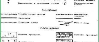
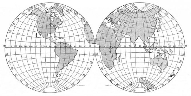
Area plan. Geographic map
Map is a reduced generalized symbolic image of the surface of the Earth (its part), other planets or the celestial sphere, built to scale and projection.
Terrain plan - a drawing of the terrain, made in conventional symbols and on a large scale (1:5000 and larger).
When making plans, the curvature of the earth's surface is not taken into account, because small areas or areas of terrain are depicted.
The difference between a site plan and a geographical map:
1) plans depict small areas of terrain, so they are built on a large scale (for example, 1 cm - 5 m). Geographic maps show much larger territories, their scale is smaller;
2) the plan depicts the area in detail, preserving the exact outlines of the depicted objects, but only in a reduced form. The large scale of the plan allows you to reflect on it almost all objects located on the ground. It is not possible to plot all objects on a map that has a smaller scale, so when creating maps, objects are generalized. The exact outlines of all objects on the map also cannot be shown, so they are distorted to one degree or another. Many objects on the map, unlike the plan, are depicted by non-scale symbols;
3) when constructing a plan, the curvature of the earth’s surface is not taken into account, since a small area of terrain is depicted. When constructing a map, it is always taken into account. Maps are built in certain map projections;
4) there is no degree network on the plans. Parallels and meridians must be marked on the map;
5) on the plan, the north direction is considered up by default, the south direction is down, the west direction is left, the east direction is right (sometimes on the plan the north-south direction is shown by an arrow that does not coincide with the up-down direction). On maps, the direction north - south is determined by meridians, west - east - by parallels.
The importance of a site plan for a person
A site plan is needed not only for studying geography, but also for the daily activities of people. Most often, a site plan is used in construction work. Builders, before starting the construction of any object, draw up a plan that helps to determine all the unevenness of the ground surface of the area. The terrain plan is often used by farmers in the process of sowing and developing new agricultural areas. Also, a site plan is indispensable during hiking trips.
Cartographic methods of representation
A method for a high-quality background. It is used to depict on a map the qualitative features of certain objects or phenomena that have a continuous distribution on the earth’s surface or occupy large areas. Its essence lies in the fact that on the map, areas that are homogeneous according to a certain characteristic(s) are identified (for example, natural zones) and painted over (or shaded) in colors selected for them (shading).
Method of habitats. Habitat is the area of distribution of a phenomenon on the earth’s surface (for example, the territory in which a certain animal lives, or the territory in which a particular agricultural crop is grown, etc.).
Isoline method. Isolines (from the Greek isos - equal) are lines on geographical maps passing through points with the same value of any quantitative indicator (temperature, precipitation, depth, height, etc.) characterizing the depicted phenomenon. For example, isotherms are lines connecting places with the same temperature; isobaths - lines connecting places with the same depth; horizontal lines are lines connecting points on the earth's surface with the same absolute height. The essence of the isoline method is that points on the map with the same values of a certain indicator are connected by thin lines, i.e., isolines are drawn.
Movement lines. Lines (arrows) show the direction of movement of any objects - air masses, winds, ocean currents, rivers, etc.
Plan
Excess
- Same as relative height.
Profile
— A vertical section, a section of any section of the earth’s surface, the earth’s crust, the hydrosphere or the atmosphere along a given line.
Picket
— A point on the ground (indicated by a sign) that serves as a reference point for installing a staff during leveling and for securing the route on the ground. Locks the specified interval.
Heel slats
— The base of the rail, designed for installation on a benchmark, shoe or crutch.
Tablet
— 1) Part of the scale, a square wooden board (side size from 40 to 70 cm), onto which drawing paper is glued. 2) A board or folder on which the compass and paper are fastened for visual photography.
Palette
— A transparent plate with a grid of lines (less often, points) printed on it, intended for calculating areas on plans and maps, counting coordinates, etc.
Design slope
— Tangent of the angle of inclination of the design line or plane.
Parallel
— A line of section of the surface of the globe by a plane parallel to the plane of the equator. All points on this line have the same latitude.
Geodetic reference
— Integration (merging) of new geodetic data with previously created ones.
Project line
— A line defining the position of structures in plan and height.
Spatial data
— Digital data about spatial objects, including information about their location, shape and properties, presented in a coordinate-time system.
Parallax
— Visible change in the position of an object (body) due to movement of the observer’s eye.
Bearing
— The angle between the direction to the observed object and one of the main planes taken as the origin of the angular coordinates. In maritime and air navigation, usually the same as azimuth.
Post-processing (satellite observations)
— Final processing of data in office conditions in order to obtain the coordinates of points.
Polygonometric point
— A geodetic point, the coordinates of which are determined by polygonometry, and the location on the ground is indicated by metal pillars or concrete monoliths.
First vertical
— A plane perpendicular to the meridian.
Polygonometry
— A method for constructing a geodetic network in the form of a broken line, in which all sides and angles are measured.
Planimeter
— A mechanical or electronic device for measuring the areas of objects according to plans and maps.
Field tracing
— Transfer of the designed route to the terrain, specifying its changes and fixing it in situ.
Direct geodetic problem
— Calculation of geodetic coordinates - the latitude and longitude of a certain point lying on the earth’s ellipsoid, using the coordinates of another point and the known length and directional angle of a given direction connecting these points.
Rectangular coordinates
— A plane coordinate system formed by two mutually perpendicular straight lines, called the x and y coordinate axes. The point of their intersection is called the origin or zero of the coordinate system. The abscissa axis is OX, the ordinate axis is OY.
Polar coordinates
— A system of plane coordinates formed by a directed straight ray OX, called the polar axis. Most often, the polar axis is taken to be the axis of the northern direction of a meridian. The origin of coordinates - point O - is called the pole of the system.
Plateau
— A vast area of the earth’s surface, which is a mountain plain characterized by significant erosional dissection.
Arbitrary projections
— Map projections that distort angles and areas. There are equidistant ones, which preserve the length scale in one of the directions (for example, along meridians or parallels), and orthodromic ones, in which the great circles of the ball (orthodromes) are depicted as straight. Used for world maps.
Pantometer
— A goniometer geodetic instrument used in surveying forests and peat bogs.
Planned aerial photography
— Photographing the terrain with the optical axis of the aerial camera in a position close to vertical.
Geodetic point
— A geodetic network point fixed on the ground.
Overlap image
— In photogrammetry, the proportion of the area of an image (aerial photograph) that is covered by an adjacent image.
Direction finding
— Determination of the direction to any object - its angular coordinates. It is carried out by optical, radio engineering, acoustic and other methods.
Planned alignment basis
— Geodetic construction at the construction site, which ensures the mutual coordination of all design elements of the complex and serves to obtain initial data for taking out into nature.
Polyconic projections
— Cartographic projections, the parallels of which are arcs of eccentric circles, and the meridians are curves symmetrical with respect to the average rectilinear meridian. Used for world maps.
Perspective aerial photography
— Photographing an area with an aerial camera, the optical axis of which is deviated from the vertical at a certain constant angle.
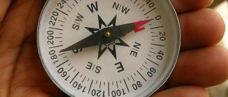
Earth's magnetic poles
— Points on the earth’s surface where the magnetic needle is located vertically, i.e. where a magnetic compass is not applicable for orientation to the cardinal points.
Measurement errors
— Deviation of the result of geodetic measurements from the true (actual) value of the measured geodetic quantity.
Paleogeographic maps
— They reflect the physical and geographical conditions of the geological past (distribution of land, sea and river networks, the nature of the continental topography, climatic features, etc.).
Determining directions, measuring distances on a plan and map
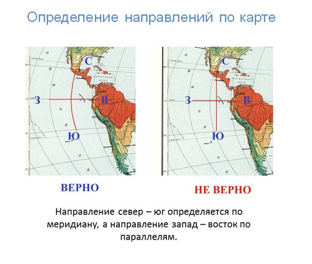
On the plan, north - south is shown by an arrow. If there is no arrow on the plan, then it is considered that north is at the top, south is at the bottom.
On the map, directions are determined using a degree network. The direction north - south corresponds to the direction of the meridians, west - east - parallels.
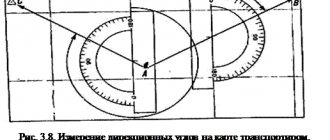
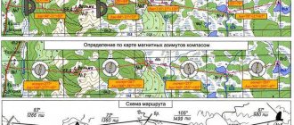
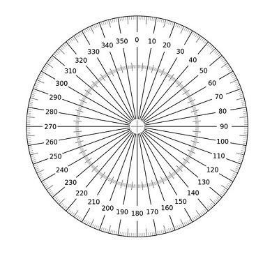
Azimuth measurements on maps are made using a protractor. Azimuth is the angle formed at a given point or on a map between the direction north and any object and measured clockwise.
So, if an object is located strictly north of the point where the observer is located, then the azimuth to it will be 0°, to the east - 90°, to the south - 180°, to the west - 270°. Azimuths can range from 0° to 360°. In order to measure azimuth on a map, you need to draw a line parallel to the north-south direction through the starting point of the determined direction. Then, also through the point, draw a line connecting the point and the object to which you want to determine the azimuth. And then, using a protractor, measure the resulting angle (azimuth), taking into account that azimuth is always measured clockwise.
Relative and absolute height
To fully convey the surface relief on the terrain plan, you should know at what height the given points are located. In order to determine whether an object is low or high, it is customary to compare its height relative to the level of the oceans or seas. Sea level height is called absolute and is designated zero (0). In the Russian Federation, the absolute height is considered to be the level of the Baltic Sea. Points that are located above the absolute height have a positive relative height (mountains, hills, hills). Points that are below the absolute height have a negative relative height (depressions, river valleys). The relative heights of objects on the earth's surface are measured using a leveling device.
Determination of geographical coordinates
Degree network and its elements. The Earth's degree network is a system of meridians and parallels on geographic maps and globes, which serves to count the geographic coordinates of points on the earth's surface - longitudes and latitudes - or to plot objects on a map according to their coordinates.
To create a degree network, certain reference points are required. The spherical shape of the Earth determines the existence of two fixed points on the earth's surface - poles. An imaginary axis around which the Earth rotates passes through the poles.
Geographic poles are mathematically calculated points of intersection of the Earth's imaginary axis of rotation with the earth's surface.
The equator is an imaginary line on the earth's surface, obtained by mentally dissecting the ellipsoid into two equal parts (Northern and Southern Hemisphere). All points of the equator are equidistant from the poles. The plane of the equator is perpendicular to the Earth's axis of rotation and passes through its center. The hemispheres are mentally separated by many more planes parallel to the plane of the equator. The lines of their intersection with the surface of the ellipsoid are called parallels. All of them, like the equatorial plane, are perpendicular to the axis of rotation of the planet. You can draw as many parallels on a map and globe as you like, but usually on educational maps they are drawn with an interval of 10-20°. The parallels are always oriented from west to east. The circumference of the parallels decreases from the equator to the poles. At the equator it is greatest, and at the poles it is zero.
When the globe is crossed by imaginary planes passing through the Earth's axis perpendicular to the equatorial plane, large circles are formed - meridians. Meridians can also be drawn through any points of the ellipsoid. They all intersect at the pole points (Fig. 4). The meridians are oriented from north to south. Average arc length of 1° meridian: 40,008.5 km: 360° = 111 km. The length of all meridians is the same. The direction of the local meridian at any point can be determined at noon by the shadow of any object. In the Northern Hemisphere, the end of the shadow always points north, in the Southern Hemisphere it always points south.
A degree network is necessary to measure the geographic coordinates of points on the earth’s surface—latitude and longitude.
Geographic latitude is the distance along the meridian in degrees from the equator to any point on the surface of the Earth. The origin is the equator. The latitude of all points on it is 0. At the poles the latitude is 90°. North latitude is measured north of the equator, and southern latitude is measured to the south.
Geographic longitude is the distance along a parallel in degrees from the prime meridian to any point on the earth’s surface. All meridians are equal in length, so it was necessary to choose one of them for counting. It became the Greenwich meridian, passing near London (where the Greenwich Observatory is located). Longitude is measured from 0° to 180°. To the east of the prime meridian up to 180° eastern longitude is measured, to the west - western longitude.
rice. 4
Thus, using a degree network, it is possible to accurately determine geographic coordinates - quantities that determine the position of a point on the earth’s surface relative to the equator and the prime meridian. For example, the geographic coordinates of Cape Chelyuskin (the extreme northern point of Eurasia) are 78° N. w. and 104° E. d.
Degree network
On the globe and all geographical maps there is a grid of thin lines, called the degree network. What is the concept and meaning of a degree network?
The Earth's degree network consists of conventional lines intersecting each other. These lines are extremely necessary for finding objects.
We are already familiar with two points - the North and South Pole. At an equal distance from the poles, a line of the degree network is drawn in the form of a circle - the equator. Lines running parallel to this circle are called parallels. They stretch from west to east. Circles are drawn through the poles, intersecting parallels, called meridians and constituting a degree network. The length of the meridians is determined from north to south.
Degree network on the globe
Knowing the direction of the length of the lines of the degree network, we can determine by the sides of the horizon where the area is located on the map.
The length of parallels along the degree network may vary. The length along the degree network of meridians is the same everywhere. As a result, the main line of the degree network is considered to be the prime or prime meridian. This main grid line extends across the London suburbs and is easy to find on the map. This meridian divides the planet into 2 hemispheres: Western and Eastern.
The most important lines of the degree network are depicted as a circle on the map. Therefore, the length of parallels and meridians along the degree network is measured in kilometers and degrees. To understand the principle of determining distance in degrees, let's figure out how the degree network works.
Take any circle and divide it into 360 parts.
We connect the division points to the center of the circle, as a result the circle will be divided into 360 angles. Each angle will be equal to 10. In the figure, each angle is equal to 100, if we were to draw through 10, they would merge with each other. The degree network on the map is indicated in the same way, after a certain number of degrees. Most often, lines are drawn through 100. The degree network is very clearly visible on the contour map.
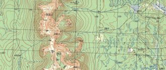
Contour map
Degrees are counted along parallels from the equator, and along meridians from the prime or Greenwich meridian. On the degree network, the equator and prime meridian are designated 00.
Using the degree network of the map, you can determine the distance between objects in degrees and kilometers. Let's look at an example.
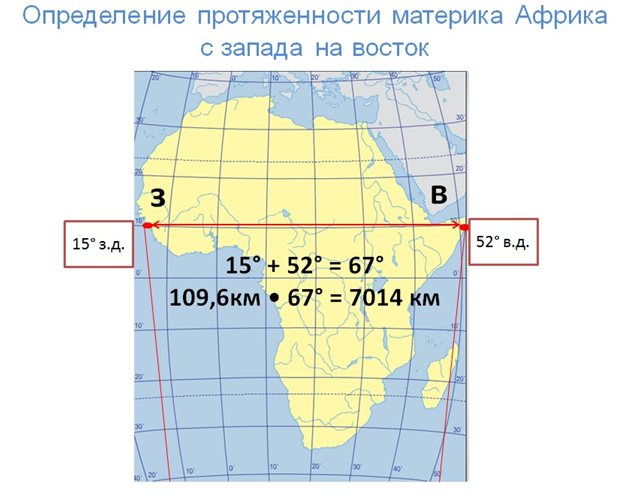
1) Let’s identify geographic coordinates: the longitude of the westernmost point on the parallel of 10° N will correspond to 15° W; the longitude of the easternmost point on the same parallel will be 52° east.
2) Let's calculate the length of the continent in degrees along 10°N latitude, to do this we find the sum of the resulting degrees 15° + 52° = 67°
3) Determine the length in kilometers at 10° N latitude. We need to find out the length of the parallel. However, all parallels are different in length. You can use the table below to determine it.
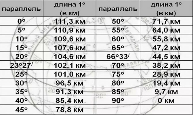
In the table we find the length of parallel 100, it is 109.6 km. We multiply it by the identified degrees
109.6 km • 67 = 7014 km
We get the length of the continent from west to east in kilometers.
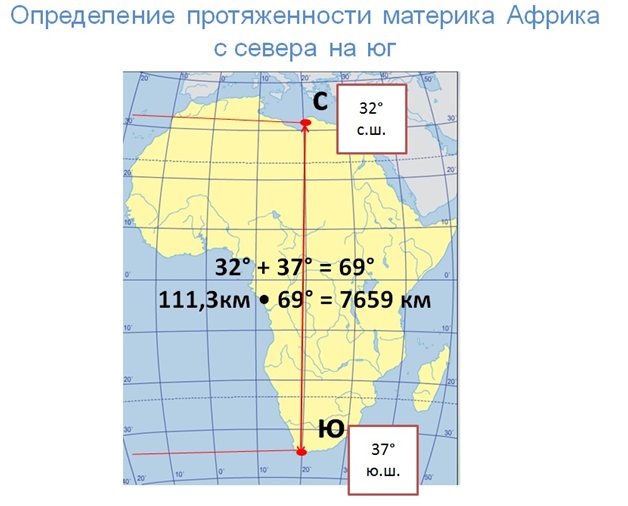
- Let's identify the geographic coordinates: the latitude of the northern point on this meridian will be 32° N, and the southern point will be 37° S.
- Let's calculate the extent in degrees along 20° East, for this we add the identified data 32° + 37° = 69°
- Let's find the length in kilometers at 20° East. To do this, multiply the length of 1° meridian by the degrees obtained
111.3 km • 69 = 7659 km
The value of 1° along the meridian always corresponds to 111.3 km, since all meridians are equal to each other.
Using the degree network, you can find the location of any area on the planet; they are called geographic coordinates.
Finding distances on a map
Scale is the ratio of the length of a line on a drawing, plan or map to the length of the corresponding line in reality. The scale shows how many times the distance on the map is reduced relative to the actual distance on the ground. If, for example, the scale of a geographic map is 1: 1,000,000, this means that 1 cm on the map corresponds to 1,000,000 cm on the ground, or 10 km.
There are numerical, linear and named scales.
The numerical scale is depicted as a fraction in which the numerator is equal to one, and the denominator is a number showing how many times the lines on the map (plan) are reduced relative to the lines on the ground. For example, a scale of 1:100,000 shows that all linear dimensions on the map are reduced by 100,000 times. Obviously, the larger the denominator of the scale, the smaller the scale; with a smaller denominator, the scale is larger. The numerical scale is a fraction, so the numerator and denominator are given in the same measurements (centimeters).
A linear scale is a straight line divided into equal segments. These segments correspond to a certain distance on the depicted terrain; divisions are indicated by numbers. The measure of length along which the divisions are marked on a scale ruler is called the scale base. In our country, the base of the scale is taken to be 1 cm. The number of meters or kilometers corresponding to the base of the scale is called the scale value. When constructing a linear scale, the number 0, from which the divisions begin, is usually placed not at the very end of the scale line, but retreated one division (base) to the right; on the first segment to the left of 0, the smallest divisions of the linear scale are applied - millimeters. The distance on the ground corresponding to one smallest division of the linear scale corresponds to the scale accuracy, and 0.1 mm corresponds to the maximum scale accuracy. A linear scale, compared to a numerical scale, has the advantage that it makes it possible to determine the actual distance on a plan and map without additional calculations.
Named scale - a scale expressed in words, for example, 1 cm 250 km. (Fig. 5):
rice. 5
Measuring distances on a map and plan. Measuring distances using a scale. To measure distance, you need to draw a straight line (if you need to know the distance in a straight line) between two points and use a ruler to measure this distance in centimeters, and then multiply the resulting number by the scale value. For example, on a map of scale 1: 100,000 (1 cm is 1 km) the distance is 5 cm, i.e. on the ground this distance is 1•5 = 5 (km). If you need to measure the distance between objects indicated by off-scale symbols, then measure the distance between the centers of the symbols.
Measuring distances using a degree network. To calculate distances on a map or globe, you can use the following values: the arc length of 1° meridian and 1° equator is approximately 111 km. The total length of the earth's meridian is 40,009 km. Due to the fact that the Earth is flattened at the poles (polar compression), the length of the 1° arc along the meridian at the equator (110.6 km) is less than at the poles (111.7 km). It is believed that the average length of 1° meridian is 111.1 km. The length of an arc of 1° along the parallels decreases towards the poles. At the equator it can also be taken equal to 111 km, and at the poles - 0 (since a pole is a point). To determine the distance in kilometers between two points lying on the same meridian, calculate the distance between them in degrees, and then multiply the number of degrees by 111.1 km. To determine the distance between two points on the equator, you also need to determine the distance between them in degrees, and then multiply by 111.1 km. To determine the distance between two points located on the same parallel, you need to know the number of kilometers corresponding to the length of 1° arc of each specific parallel.
Definition of zone and zone time
Time Zones. Local and standard time. Solar time at points located on the same meridian is called local . Due to the fact that at every moment of the day it is different on all meridians, it is inconvenient to use. Therefore, by international agreement, standard time was introduced. The entire surface of the Earth was divided along the meridians into 24 zones of 15° longitude. Zone time (the same within each zone) is the local time of the median meridian of a given zone. The zero belt is a belt whose median meridian is the Greenwich (zero) meridian. From there, the belts are counted to the east.
Since 2014, 11 time zones have been established in Russia. The starting point for calculating the local time of time zones is Moscow time - the time of the II time zone (see map). Thus, the difference in time between the first time zone and the eleventh is 10 hours.
Conventionally, it is believed that a new day begins in the 12th time zone (through which the 180° meridian passes - the international date line). West of the international date line, a new day begins (according to the calendar). Therefore, in the logbook of a ship sailing from west to east, one day must be counted twice, and a ship moving from east to west, as it were, “skips” one day, after December 31 it immediately ends up on January 2.